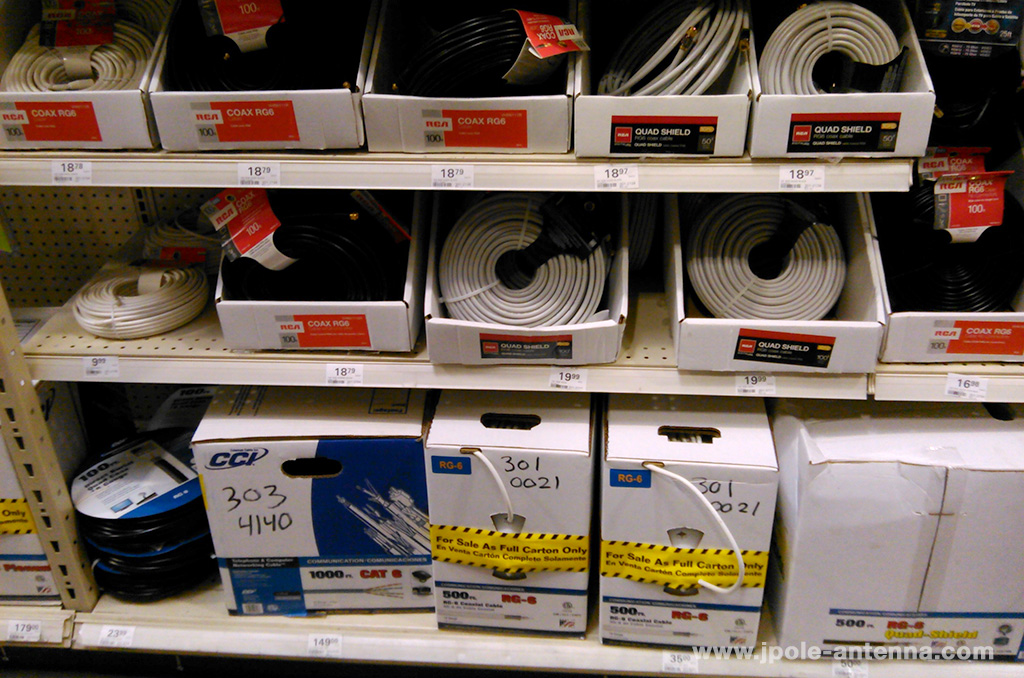
As ham radio operators, we’re always looking for a way to save a buck. I’ll frequently dig through a free bin of part, hoping to scavenge something for the next project. This scavenger mentality extends to coax feed-line. High quality coax cable can be expensive. That’s why we love a deal when can find it. The cable television companies go through miles of coax cable on a daily basis. Often a ham can pick up free pieces and reel ends for pennies on the dollar. Or just take a trip through your local home improvement store and you’ll see 100 foot spools of 75 Ohm RG-6 for a fraction of the cost of similar 50 Ohm RG-8U.
 But are 75 Ohm cables really a good bet? Will it work for ham radio? Or am I setting myself up for aggravation? This article explores the good and bad of 75 Ohm coax cable.
Impedance mismatch of 75 Ohm Cable
RG-59 and RG-6 are 75 Ohm coaxial cables designed for cable television applications, they tend to have wide frequency response and low line loss. They also have an impedance of 75 ohms, which is a standard for coax cable used in the broadcast industry. You can use these cables with a 50 Ohm amateur radio antenna system, but because of the impedance mismatch, your SWR will be a little higher. For example, if everything else is balanced out, using the 75 ohm cable with a 50 Ohm antenna will increase your SWR to 1.5:1 at the transmitter.
For HF, this mismatch isn’t a big deal
Now this really isn’t a big deal as 1.5:1 is still within the 2:1 SWR limit that most modern ham radio transceivers will tolerate. In HF applications, the impedance mismatch can be further reduced by the use of an antenna tuner. The tuner gives the transmitter the 50 Ohm match that it expects. So for their HF antenna systems, many hams will use RG-59 or RG-6 because it’s cheaper than 50 Ohm RG-58 or RG-8, and any mismatch can be resolved by the tuner. It works, but it’s not an ideal situation.
But you also don’t have to live with the mismatch on VHF
VHF/UHF is another story. RG-6 is rated for applications below 150 MHz, so it can be used with transmitters and antennas on the 2 meter band. but above the frequency, the losses are going to be so high, that you might as well invest in quality 50 Ohm cable. While resolving the impedance mismatch isn’t critical (you can still run with an SWR of 1.5:1) most VHF rigs don’t offer antenna tuners to create a 50 ohm match for the transmitter. You’ll just have to take a small performance hit in exchange for saving money.
There are two ways to deal with this mismatch. They don’t require a tuner, but you will only be able to effectively use the cable run for a single frequency or band. By the way, these methods also work on HF too.
The first method is to measure and cut your coax so the entire cable run can be measured in 1/2 wavelength multiples. For the two meter band, a half wave is approximately 38 inches. Keeping your cable length within these 1/2 wave multiples will present a near 50 Ohm match at the transmitter end of the line. But how does this work?
Say you where to take a length of 50 Ohm coax and put a 100 Ohm resister at the end. If you where to measure the impedance at the other end, what would it be? Not necessarily 50 Ohms. The reason is that coax offers a mix of resistive and reactive elements that change with the length of the coax. For example, using 1/4 wave length multiples of 75 Ohm coax will give you your 100 Ohm resister a 50 Ohm impedance at the transmitter end. Now if you were to substitute that resister with a 50 ohm antenna, using 1/2 wave multiples of 75 Ohm coax would give you a 50 Ohm impedance. Not too shabby.
This practice works well with VHF as the 1/2 waves are relatively short, so you don’t need to contend with a bunch of extra coax cable. But as you lower the frequency, those wavelengths increase, to the point were you’ve got up to 120 feet of extra cable on the 75 meter band.
Another method is to use a transformer. Like I mentioned earlier that transmission line offers a mix of resistive and reactive components based on length, you can change the impedance of a 75 Ohm coax cable line by using short 1/12 wavelength sections of 75 and 50 Ohm coax at the feed point and transmitter. This method again only works for a particular frequency, but you will have enough bandwidth to still cover the 2 meter VHF band.
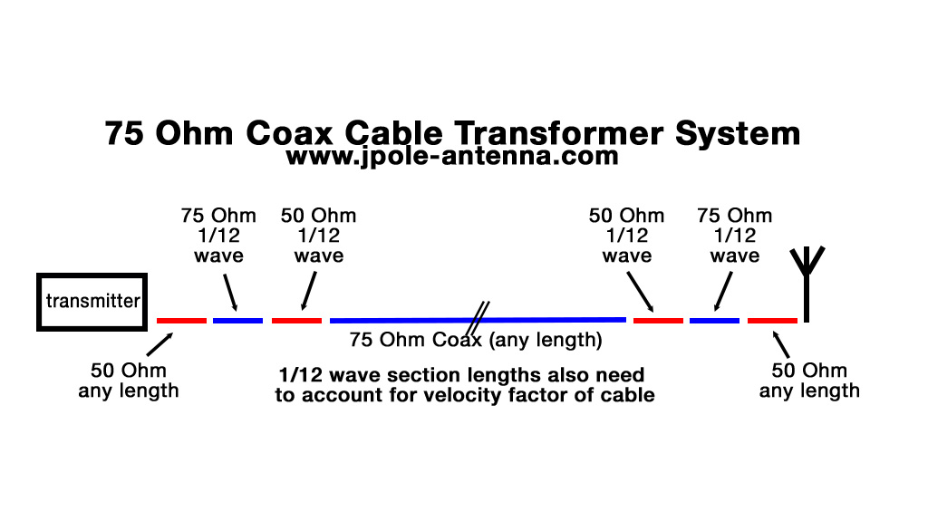 A 1/12 wavelength section of coax at 146 Mhz will be 6.3 inches long. But don’t cut the section to that length, you will need to shorten the cable based on the velocity factor of the cable. This value could be anywhere from .60 to .90. The VF is sometimes printed on the cable, otherwise you’ll have to look it up on the specification sheet for the type of coax you’re using. Put the sections inline like the diagram and do a final check with an antenna meter or analyzer.
If I was using 75 Ohm cable, for simplicity’s sake, I’d use the transformer for HF applications were it’s easier to cut longer pieces of coax into 1/12 wave sections and rely on running my feed line in 1/2 wave multiples for VHF.
RG-6 connectors
The biggest challenge in using 75 Ohm coax cable with your amateur radio setup is not the impedance, but attaching the connectors to the cable. RG-6 and RG-11 both have an aluminum shield material that can be quite difficult to solder. Attaching a PL-259 connector to the cable, in the normal fashion by soldering the braid to the barrel of the connector will often result in a weak connection that will corrode or break in time. That is, if you can get it soldered. What often happens is the dielectric of the cable starts to melt before the solder begins to flow.
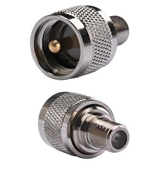
A better solution is to use crimp F connectors designed for for RG-6 or RG-11 and an F to Pl-259 adapter. The F connectors are sturdy and reliable, the crimping process is designed for this style of cable. The additional cost of the adapters is marginal considering the per foot costs of RG-6 to 50 Ohm RG-8U. Here’s a great set of step-by-instructions on how to properly crimp RG-6 cable.
Conclusion
I have no problem with using 75 Ohm cable for HF applications and in certain applications for transmitters up to 150 MHz. Cable coax seems to be just as well suited on the lower frequencies of the HF bands as does 50 Ohm coax. But at the VHF range and beyond, I find the losses of the cable to be too great. With VHF/UHF communications, were transmitter power can be easily eaten up be lossy coax, you’re better off in putting your money into high quality coax cable. A wise ham once told me: “purchase an affordable antenna and invest your money into high quality coax.” It’s easier to replace an antenna than it is to re-do cable runs.
I work for Directv and our coax is swept to 3000 mhz. We run a network on it that runs from 3mhz to 1760mhz . That’s way above the 150 mhz mentioned.
Dave,
Yes, you are correct that RG-6 & RG-11 will work for a wide range of frequencies. But as you go up in frequency, the feed line will attenuate the signal. For example, at 150 Mhz, RG-6 will have 2.8 db of attenuation per 100 feet. This isn’t so bad, but when you increase the frequency to 450 MHz, the attenuation also increases to 4.3 db per 100 feet. If you are operating a VHF/UHF transmitter and are concerned about the efficiency of your feed line, then you will want to use something with lower loss characteristics.
Michael
If you want to learn more about coaxial cables parameters and how to choose them check this article http://epricedtech.com/Coaxial-Cables-Common-Parameters
more bout coaxial cable quality check this http://epricedtech.com/Coaxial-Cable-quality-coax-rg6-rg59-rg8x-review-Article
can RG-6 cable be used for my 50 ohm ground plan ant. for 28.300 to 28.500 MHz with out alot of trouble i need around a 75ft. run to transmitter?? thanks much ed kk4asi
Ed,
You can use RG-6 to feed your 10 meter ground plane antenna. To maintain a 50 Ohm impedance at your feedpoint, you should cut your cable in 1/2 wave multiples. For 10 meters a half wave is about 16 feet, so to stay within that multiple, your cable should be 80 feet long.
Michael
Hi Michael.
For many years I have been aware that the both the MOD and amateur communication equipment etc favour 50ohm coaxial cable feeds.
We see numerous articles on both wideband and narrow band, straight forward. 4:1 baluns for.50ohms resuting in a final termination of 200ohms.
This would open up a great possibility for 200ohm twin feeder antenna systems etc.
Have you ever seen 200ohm twin feeder commercially availlable?
I would love to hear if any 200ohm twin feeder exists, I have always nade my own.
If 75ohm coaxial cable had been the standard there has always existed an easily available range of various 300ohm twin feefer cable to make up 300ohm feed lines and folded dipoles etc!
73s Keith de G8SYA
The 50 ohm antenna is far less common than most believe. I use RG-6 on a 3-band (40, 20, 15) inverted vee with no problems. The antenna has resonant (more or less) segments for 40 and 20, and the 40 works as 1 1/2 wave on 15. Termination is a bit more difficult, but my Kenwood TS-120S tolerates any mismatch with ease. I also use it on a 2 m 3 ele quad and have no trouble hitting repeaters 50 miles with my UV5R5. Best of all the RG-8 was free. I encourage others to experiment with it.
Henry, W5GEN
I really enjoyed your article. I’ve worked in the cable industry for 10 years and recently have taken an interest in CB radios. It’s very easy for me to acquire RG 59, and adapters. I’m going to be outfitting a few of my company’s trucks with CB radios, and can easily make my rg59 cables to the exact length I need. In your opinion, would it be acceptable to use the 59, with the appropriate adapters and a tunable antenna to calibrate my SWR, or bite the bullet and get RG8?
William,
RG-6 or RG-59 will work for you if you keep the length in 1/2 wave multiples. For 27Mhz, that would be 17.3 feet. Keeping your cable in multiples of that length will minimize losses due to the impedance mismatch. I think, overall, you will have less loss if you use RG-6 cut to a half wave multiple than you would in using RG-8X cut to whatever length.
I hope this helps you out. Please let me know if you have any other questions.
Michael
Its interesting, I’ve always used the wavelength rule on all of my coax when I trim it up. I work at a university setting where we handle the A/V needs of a medical campus. We pull a lot of RG-6 to replace with Cat-6 shielded for our Crestron DM plant. I have reels, some really huge of RG-6. I’ve resisted using it for my Ham applications. I think eventually we will send it to state surplus auction.