As the late spring and summer months heat up, six meters comes alive. Known as the Magic Band, the six meter band can be mysterious, unpredictable, and downright fun. You never quite know when the band will open and where it will take you. Every year our club’s Field Day operation puts a six meter station on the air. But along with the unpredictable nature of six meters, we never quite know if six will ‘open up’ and give us a flurry of activity or stay dormant for the weekend.
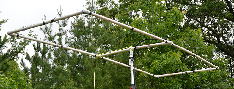
At last year’s Field Day I built a six meter antenna to replace a slightly damaged 3 element beam. In selecting antenna designs I wanted something that was easy to build, inexpensive, and had good performance. I settled on the Moxon antenna design as it satisfied all three requirements.
The Moxon Antenna, designed by Les Moxon G6XN (SK), is a compact two element beam antenna with about 5.5-6 dbi of gain and a 25db front to back ratio.
Les was looking for a compact design for the HF bands when he asked the question: what if I fold in the ends of a dipole antenna to reduce the amount of space an antenna occupies. After a bit of testing and design, the Moxon Antenna was born.
What makes the Moxon an appealing antenna? By folding the ends of the elements, the Moxon is about 25% narrower than a conventional dipole or yogi antenna. Moxon’s can be built out of wire and supported on a frame, or for the lower frequencies, the elements can be tied and guyed in place. Wouldn’t it be great to have a 75 meter beam antenna with 6dbi of gain pointed towards Europe? If you have the space, you can do that with a Moxon.
Building the Moxon Antenna
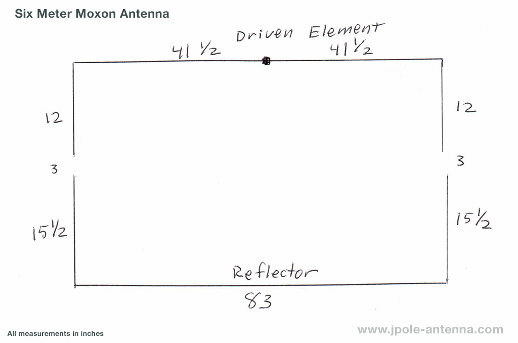
The first step in building my Six Meter Moxon was to calculate the dimensions. There are a variety of applications and online calculators that will make easy work of breaking down the formula into the dimensions necessary for your antenna. I chose to use the online Moxon Rectangular calculator by AB1JX, but other calculators will give you similar results. Using these measurements gave me an antenna that was about 1.4:1 SWR at my target frequency of 51 MHz along with a 50 Ohm match at the feedpoint. I ended up ‘pruning and tuning’ the antenna another half inch or so to get it to the closest match possible. Quick tip: when cutting your wire elements, add a bit of extra wire for twisting on or soldering the wire to the UHF connector or a coax pigtail. You can always trim wire to get it in tune, but it’s harder to add wire.
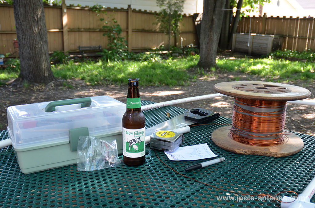
Materials List
- 19 feet 14 AWG copper or copper clad hard drawn steel wire
- 3 ten foot sections 1/2 inch Schedule 1120 thin wall PVC
- 4 1/2 inch PVC elbows
- 3 1/2 inch PVC tees
- Pipe dope
- SO-239 Female UHF connector
- Electrical tape or wire ties
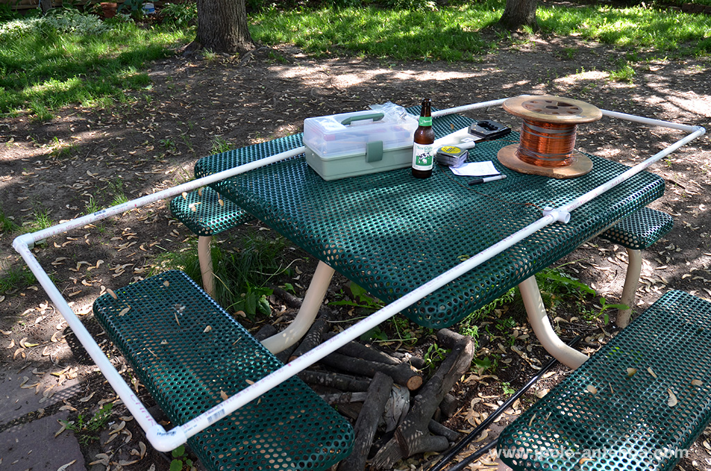
Build the PVC Frame. Cut four sections of PVC 41 inches long, two sections 30 inches long, and two sections 14 inches long. Assemble the frame, dry fitting the pieces first in case any tweaking of measurements need to be done. Once you are satisfied, use pipe dope to make the connections permament.
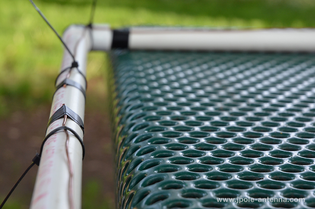
Cut the wire. Cut two pieces of wire 53 1/2 inches long (add an extra 1/2 inch or so for connecting the wire to the UHF connector) and one piece of wire 114 inches long. Fashion a 90 degree bend at one end of two shorter pieces at the 12 inch mark. Make a 90 degree bend at 15 1/2 inches on each end of the long piece. Lay the wires on the dry-fit frame and make adjustments to the dimensions of the frame, if necessary. I like to use wire ties to temporarily hold the wire on the frame but will securely tape the wire to the frame once all tuning adjustments are made.

Solder or twist-tie the shorter wires to the UHF connector. It doesn’t make a difference which wire is connected to which side, just as long as one wire is connected to the center pin and the other to the chassis.
Test your handiwork. Your antenna should come close to 1:1 SWR if you use the dimensions on this page. If you used the calculator to determine your dimensions, you will come close (1.5:1 or less), but may end up trimming and adjusting to get the SWR down lower. When trimming the antenna, be sure to consistently take a little bit of wire off both sides of the driven and reflected elements, so that the dimensions stay consistent on all sides. If you are using copper electrical wire with the insulation still intact, your elements may end up shorter due to the velocity factor of the wire. Rule of thumb for 12 or 14 AWG THHN copper wire is .975 or 2 – 3% shorter than bare copper wire.
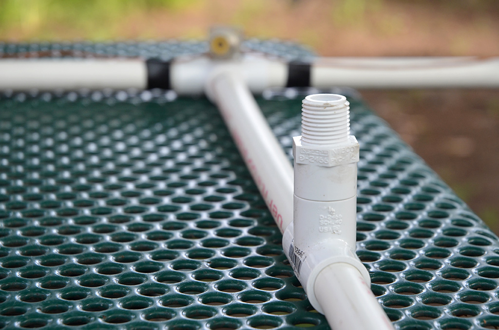
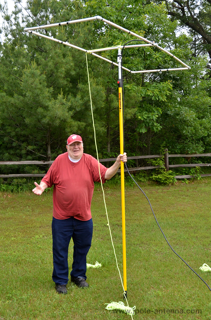
I designed my Moxon for temporary use at Field Day, so the usually put the center T connector into the top of a push-up painters pole, and tie a rope off the end to rotate it. In this configuration, the antenna is horizontally polarized, but you can add some extra PVC to mount the antenna vertically for 6 meter FM work.
In fact, the appeal of the Moxon is its versatility. I’ve seen models made with PVC frames, bamboo or fiberglass fishing rods used as spreaders, and even out of aluminum tube. No two Moxon antennas are quite alike and Steve’s K6SGH, site the Moxon Antenna Project has a large gallery of Moxon antenna designs. There really isn’t a wrong way to build the Moxon.
Operation
The Moxon is a two element beam antenna. You can use a small rotor to turn the antenna or fix it in a static direction. I prefer to use a rope as an ‘armstrong rotor’ for mine. The driven element and feedpoint is the front of the antenna, so tie the rope on the back and use the feedpoint to ‘aim’ the antenna in the direction you want to transmit.
Software modeling of the Moxon antenna shows that it has about 6dbi of gain and about a 25db front to back ratio. These are great characteristics for a low band VHF and HF style antenna as selectivity is preferred over big gain. In last year’s field day operation, the bands were not in our favor, Monitoring the 6 meter calling frequency, we did receive a few signals, but did not get that magic band opening needed to really test the antenna. But I’m confident this antenna is a winner and it will be out again at this year’s field day operation.
Conclusion
What’s next? My next project is to build Moxons for 2 meter and the 70cm ATV bands. A super compact UHF Moxon for my amateur television kit would be a great addition. I’m also working on refining my design in the hopes to offer a commercial version of this antenna. Have you built or used a Moxon antenna? Why not tell us your experiences in the comments below.
This looks very similar to the one I’ve built. I’d not made the ends solid as I need to fold it up for portable use, but it does work well. Used 8AWG PVC covered wire inside the 20mm conduit and a coax balun and insulators made from bits of coat hanger.
Thanks for the plans. I built mine using the specs you gave. It was hard to get it under 1.7:1 but I used a tuner and accepted it was tough to get the gap spacing right. Wire moves around even when taped!
First 6m QSO was a 11 mile contact. Signals were strong both ways. Next one was 1100 miles. Worked Tijuana, Mexico, as a -1db on JT mode! Sure helps he was using a virtual 6m antenna farm, but I had the Moxon pointed NORTH. So it was strong as heck off the backend!
Many thanks. I’m graduating up to a 4 or 5 el 6m yagi, but this I built for $3.
K3RW
Greg,
Thanks for your signal reports on the Moxon antenna. It’s a great little directional antenna and will work great when the 6 meter band is open. When I built mine I got the SWR down to about 1.4:1, but the resonance was perfect and I had a 50 ohm match, so all was good. If you are getting at 50 Ohm match with your 1.7:1 SWR, all will be good.
I built a 6 meter Moxon today based on your description. Came out very nice. SWR is 1.28 on 50.125 mhz. Thanks for the nice work!
Just wanted to drop a quick note of thanks. Built mine yesterday and SWR ranges from 1.3 to 1.7 across the entire 6m band without any further adjustments. It was a ball to make and seems to be working real well…if only the band would cooperate long enough for a QSO now!
I built this last night, hooked it up to my IC-7300… the SWR meter in the 50MHz range is ALMOST 1:1
Only cost me about $25 in materials at Home Depot